Design Overview
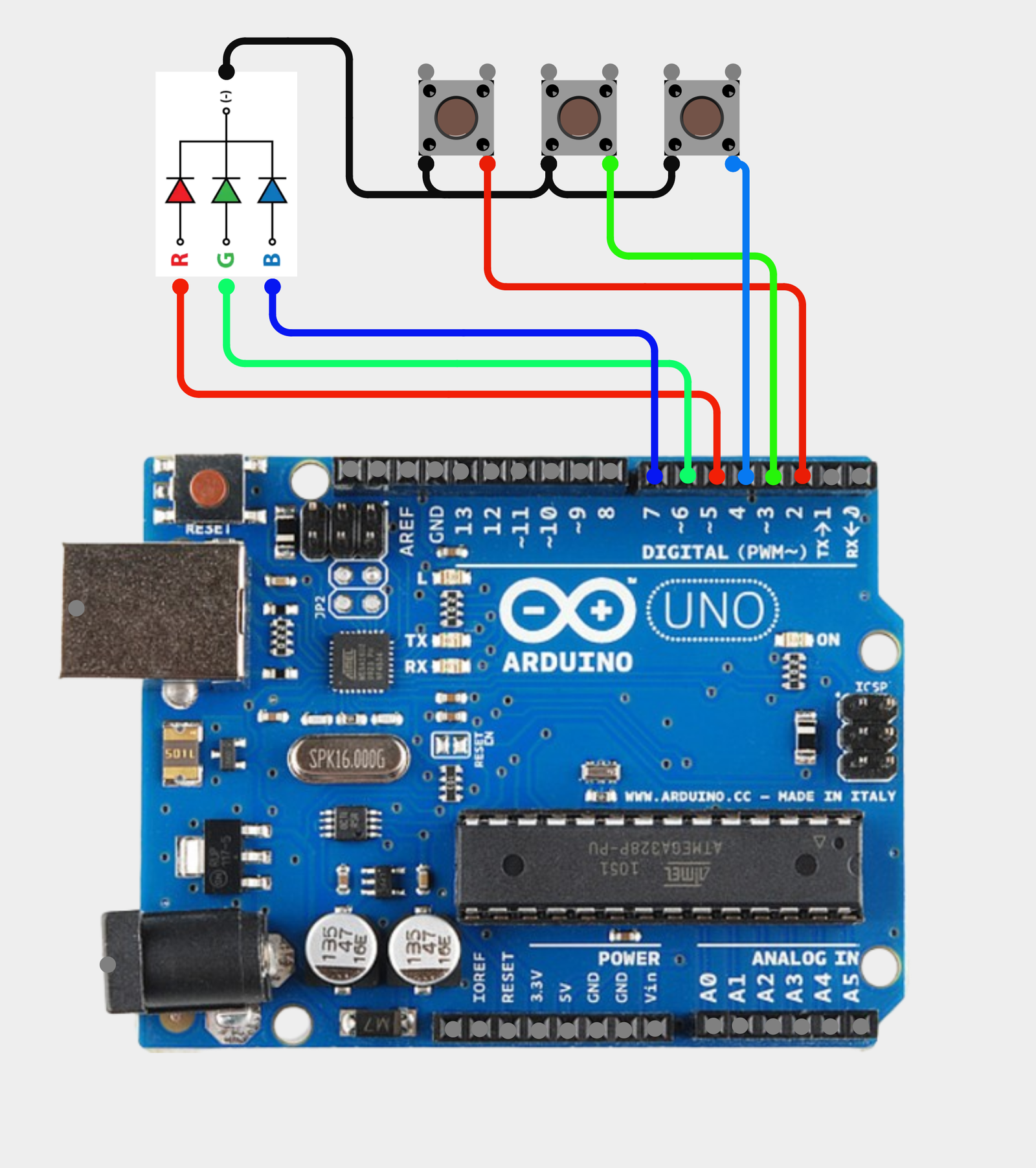
The Arduino UNO in this circuit has the following pin connections and purposes:
These connections suggest that the Arduino UNO is used to read the states of three pushbuttons and control an RGB LED.
Working Principle
Push buttons or switches help to connect two points in a circuit when you press them. As a consequence, the circuit design focus on using the internal pull up of the Arduino board for push button. This implies that, the circuit will not be using an external pull up/down resistor for our push buttons. In this circuit configuration, there are three separate push buttons that turn ON RED, GREEN and BLUE of the RGB component accordingly when pressed. In other words, the "R," "G," and "B" buttons will, respectively, switch on the red, green, and blue lights. The push button circuit is simple and may be used for light control, DC or AC motor control, security system and access control.
Code (Tested with Arduino Uno)
/*
*Push button with internal pull up of the Arduino board
*Push button without external pull pull up/down resistor
*Note: RGB common = Ground
*/
#define BUTTON_PIN_1 2 // Arduino Pin 2 = Button 1
#define BUTTON_PIN_2 3 // Arduino Pin 3 = Button 2
#define BUTTON_PIN_3 4 // Arduino Pin 4 = Button 3
#define RGBLEDPin_RED 5 // Arduino Pin 5 = RED Anode (+)
#define RGBLEDPin_GREEN 6 // Arduino Pin 6 = GREEN Anode (+)
#define RGBLEDPin_BLUE 7 // Arduino Pin 7 = BLUE Anode (+)
//Variable Declaration
byte buttonState1;
byte buttonState2;
byte buttonState3;
void setup()
{
Serial.begin(9600); // TX-RX serial communication with Arduino (9600 baudrate)
pinMode(BUTTON_PIN_1, INPUT_PULLUP); // Configure with internal pull up resistor of the Arduino board
pinMode(BUTTON_PIN_2, INPUT_PULLUP); // Configure with internal pull up resistor of the Arduino board
pinMode(BUTTON_PIN_3, INPUT_PULLUP); // Configure with internal pull up resistor of the Arduino board
pinMode(RGBLEDPin_RED,OUTPUT); // Configure as digital output
pinMode(RGBLEDPin_GREEN,OUTPUT); // Configure as digital output
pinMode(RGBLEDPin_BLUE,OUTPUT); // Configure as digital output
digitalWrite(RGBLEDPin_RED,LOW); //Turn OFF
digitalWrite(RGBLEDPin_GREEN,LOW); //Turn OFF
digitalWrite(RGBLEDPin_BLUE,LOW); //Turn OFF
}
void loop()
{
buttonState1 = digitalRead(BUTTON_PIN_1);
buttonState2 = digitalRead(BUTTON_PIN_2);
buttonState3 = digitalRead(BUTTON_PIN_3);
if (buttonState1 == LOW) //Note: we read low state since it uses internal pullup resisor
{
digitalWrite(RGBLEDPin_RED,HIGH); //Turn ON
Serial.println("Button 1 is pressed");
digitalWrite(RGBLEDPin_GREEN,LOW); //Turn OFF
digitalWrite(RGBLEDPin_BLUE,LOW); //Turn OFF
}
if (buttonState2 == LOW) //Note: we read low state since it uses internal pullup resisor
{
digitalWrite(RGBLEDPin_GREEN,HIGH); //Turn ON
Serial.println("Button 2 is pressed");
digitalWrite(RGBLEDPin_RED,LOW); //Turn OFF
digitalWrite(RGBLEDPin_BLUE,LOW); //Turn OFF
}
if (buttonState3 == LOW) //Note: we read low state since it uses internal pullup resisor
{
digitalWrite(RGBLEDPin_BLUE,HIGH); //Turn ON
Serial.println("Button 3 is pressed");
digitalWrite(RGBLEDPin_RED,LOW); //Turn OFF
digitalWrite(RGBLEDPin_GREEN,LOW); //Turn OFF
}
delay(100);
}