Design Overview
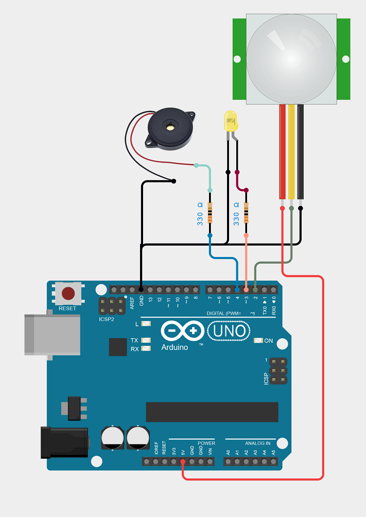
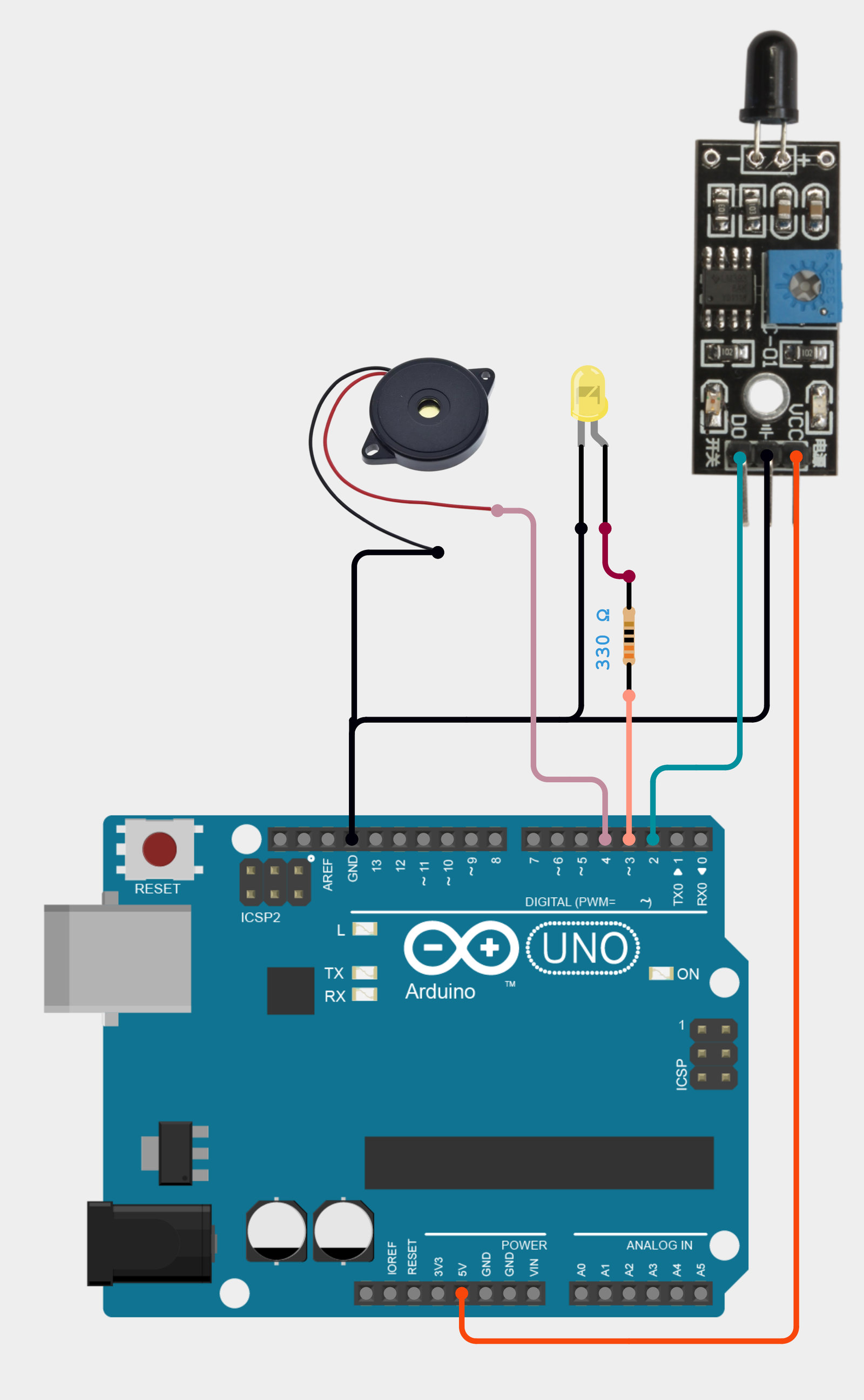
The Arduino UNO in this circuit has the following pin connections and purposes:
These connections allow the Arduino UNO to interact with the flame sensor, control the LED, and activate the buzzer based on the sensor's input.
Working Principle
A flame sensor is a device that detects the presence of fire or other light sources within a certain wavelength range, which is commonly between 760nm and 1100nm. The flame sensor module operates in a straightforward manner. It is based on the idea that infrared radiation is released by a heated body. This radiation will usually be strong for a fire or flame. Thus, an infrared photodiode will be used to detect this IR radiation. Depending on the infrared radiation the photodiode senses, its conductivity will change. An LM393 is used by the Flame Sensor Breakout Board to compare this radiation, and the digital output is altered when a threshold value is met. Consequently, the circuit implies that an alert will sound and the LED will light on anytime a flame or fire is detected. The fire detection circuit is straightforward and practical because it enables early fire detection, which gives vital time to notify building occupants to leave and may reduce damage by facilitating a quick response to a fire emergency, so saving lives and property.
Code (Tested with Arduino Uno)
void setup()
#define FlamePin 2 // Arduino Pin 2 = Flame IR Sensor Output
#define LEDPin 3 // Arduino Pin 3 = LED Anode (+)
#define SoundPin 4 // Arduino Pin 4 = Buzzer (+)
int FlameSensor = HIGH; // state of sensor
void setup()
{
Serial.begin(9600); // TX-RX serial communication with Arduino (9600 baudrate)
pinMode(FlamePin,INPUT); // Configure as digital input
pinMode(SoundPin,OUTPUT); // Configure as digital output
pinMode(LEDPin,OUTPUT); // Configure as digital output
}
void loop()
{
FlameSensor = digitalRead(FlamePin); // reading from the sensor
if (FlameSensor == LOW)
{
Serial.println("Flame Detected");
digitalWrite(LEDPin, HIGH); // Turn ON
playMelody(); // Turn ON Sound
}
else
{
Serial.println("No flame Detected");
digitalWrite(LEDPin, LOW); // Turn OFF
noTone(SoundPin); // OFF SOund
}
}
void playMelody()
{
// Play a simple melody: C4, E4, G4, C5
tone(SoundPin, 262, 200); // C4
delay(200);
tone(SoundPin, 330, 200); // E4
delay(200);
tone(SoundPin, 392, 200); // G4
delay(200);
tone(SoundPin, 523, 200); // C5
delay(200);
}