Design Overview
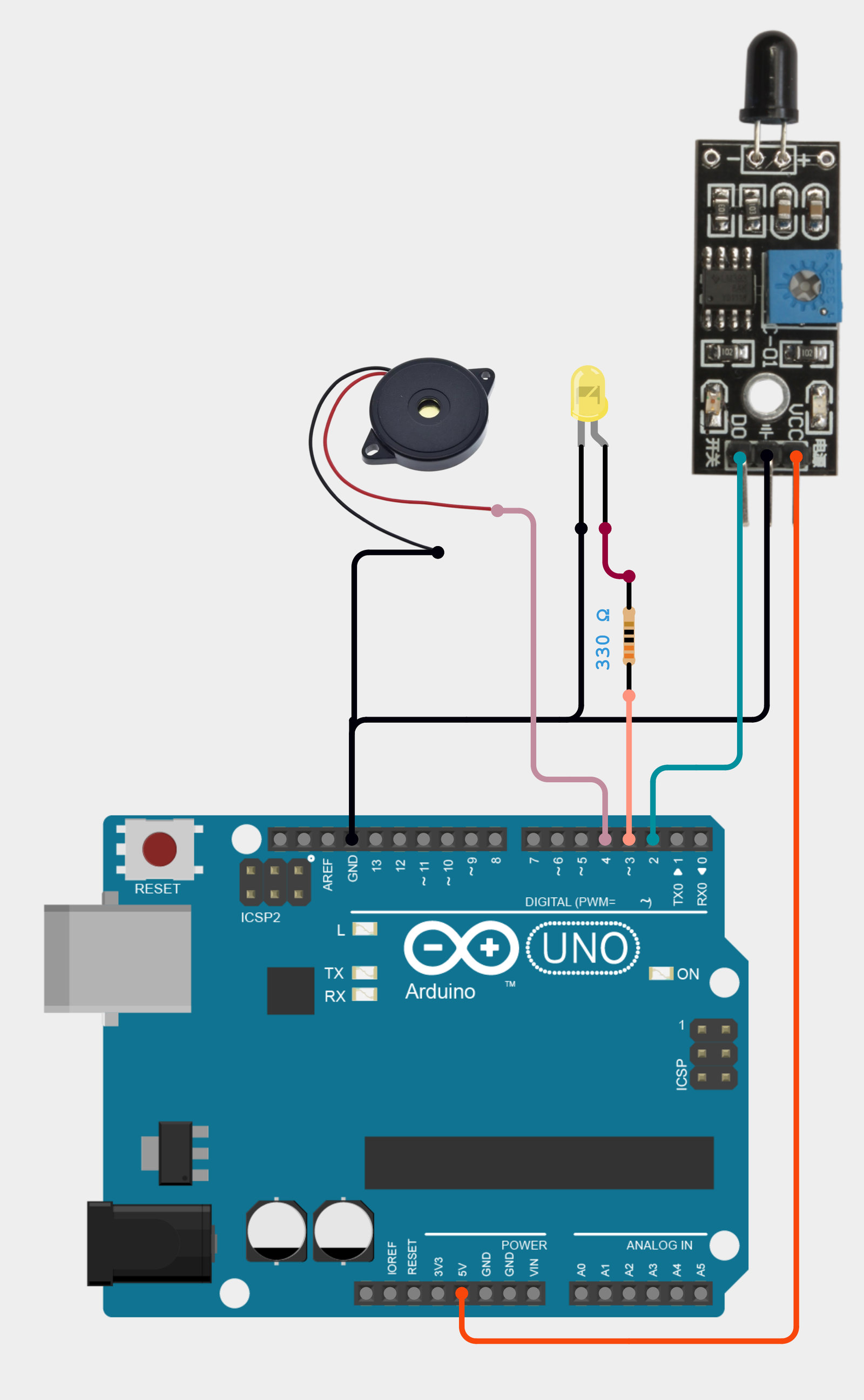
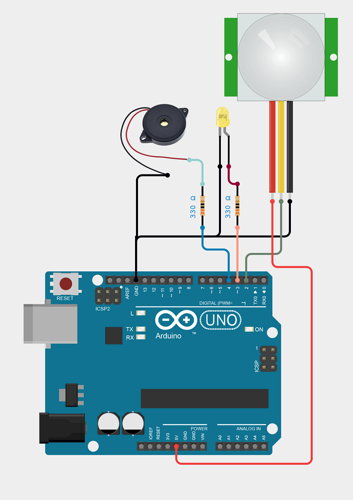
The Arduino UNO in this circuit has the following pin connections and purposes:
These connections allow the Arduino UNO to interact with the PIR sensor, control the LED, and control the buzzer.
Working Principle
At temperatures higher than absolute zero (0 Kelvin, or -273.15 °C), thermal energy is released as infrared radiation by all things, including the human body. A thing emits more radiation the hotter it is. Due to its emission at infrared wavelengths, this radiation is invisible to the human eye. Such quantities of infrared radiation are specially detected by the PIR sensor. You may use the PIR sensor to determine when an animal or human enters or exits the sensors field of view. The majority of contemporary security systems, automated light switches, garage door openers, and other devices that need to respond to motion have this sensor.
As a consequence, the circuit recommends that anytime a body movement is detected, the system first does a few seconds of scanning to guarantee that the body is detected, after which an alarm will sound and the LED yellow will continue to blink until no more motion is detected. The motion-detecting circuit is simple and may be used for energy efficiency, home automation, robotics, access control, and security systems like burglar alarms or trail cameras.
Code (Tested by Arduino Uno)
#define PIRPin 2 // Arduino Pin 2 = PIR Sensor Output
#define LEDPin 3 // Arduino Pin 3 = LED Anode (+)
#define SoundPin 4 // Arduino Pin 4 = Buzzer (+)
//Variable Declaration
int PIRSensor;
void setup()
{
pinMode(PIRPin,INPUT); // Configure as digital input
pinMode(SoundPin,OUTPUT); // Configure as digital output
pinMode(LEDPin,OUTPUT); // Configure as digital output
}
void loop()
{
PIRSensor = digitalRead(PIRPin); // Read Passive Infrared Sensor State (LOW or HIGH)
if(PIRSensor==HIGH)
{
//Motion detected
// Note:Scan time setting depends on application
delay(2000);//Lets scan for 2 seconds for False detected
if(PIRSensor==HIGH)
{
//Turn on sound and blink LED
digitalWrite(LEDPin,HIGH); //Turn ON
digitalWrite(SoundPin,HIGH); // Turn ON
delay(1000);
digitalWrite(LEDPin,LOW); //Turn OFF
}
}
else
{
digitalWrite(LEDPin,LOW); //Turn OFF
digitalWrite(SoundPin,LOW); // Turn OFF
}
}